

Select your language

- Details
- Category: Museo
-
Also available:

Ace railway traffic control
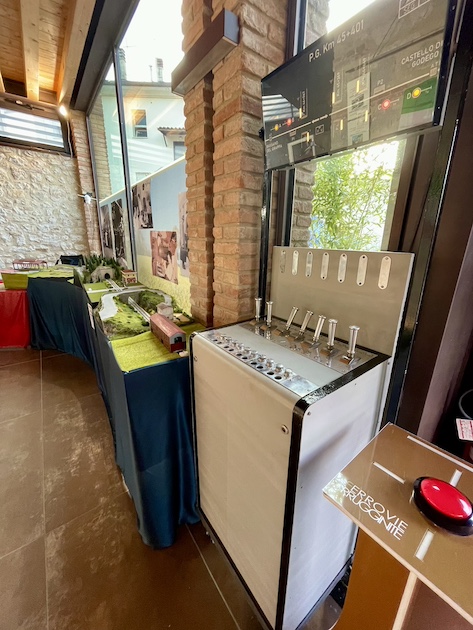
The “Apparato centrale elettrico a leve individuali” was an electro-mechanical interlocking control system used in railway stations and various service locations to manage the operation of the elements that served (and still serves) train traffic. It is often simply called an electric central apparatus, from which the acronym ACE derives, although this term generally applies to all electric central apparatuses.”
A bit of history
Italy's first electric central apparatus, in which railway switches were operated by electric motors, was installed in 1924 at Sestri Levante station. This system was based on the CIWFS model, with an experimental light-signaling system for warning and protection, along with semaphore signals for departures. This apparatus was of American origin (US&S). The following year, similar apparatuses were installed at other stations, built by AEG under license from OMS (Officine Meccaniche Servettaz) of Savona. Later, starting in 1935, the model proposed by IVEM of Vicenza was introduced at several stations, including Mortara, which was of the cabin type. In 1936, Ferrovie dello Stato (FS) decided to standardize the apparatuses, leading to the creation of the unified panel model for the FS 1936-type electric central apparatus, which is still in use at many stations on the network today.
After World War II, in order to solve some problems with the original design — such as the extension of the FS panel below floor level and its considerable weight (from 950 kilograms for a 10-lever module up to 3.3 tonnes for a 30-lever module) — SASIB, which had itself built many Central Apparatus installations with the FS-type panel, proposed a new panel model. This new model became even more widespread than the previous FS type, thanks to its ability to handle up to two keys per lever, which made it possible to build electric central apparatuses or apparatuses for manually operated switches using the same panel type, while offering greater modularity (in addition to the 5- and 10-lever modules, a 7-lever module was introduced, allowing various lever combinations to be created without wasting space).
Characteristics
On the control panel of an ACE system, there are as many levers as there are switches to be operated, signals to be positioned, and level crossings to be controlled.
The system uses electrical connections to move the switch points, position the signals, control the station's level crossings, and monitor the status of track circuits. A safety mechanism prevents commands that are incompatible with other operations in progress.
Some levers are equipped with an electric lock that prevents operation unless certain conditions are met. For example, it is not possible to move a switch lever if a train is positioned above it. In the event of a fault, some of these electrical controls can be bypassed using sealed buttons located above each lever or on a separate electrical panel.
Each lever, depending on its function, is identified by a color:
| Colour | Function |
| Brown | Disabling (locks switch levers for transit along the correct track) |
| Black | Switch (operates the points) or electric point clamp (locks a manually operated switch) |
| Light blue | Level crossing |
| Blue | Route (locks the path for a train and opens the lower signals) |
| Purple | Shunting route (locks the path for a shunting movement and opens the lower signals) |
| Red | 1st or 2nd category signal |
| Yellow | Warning signal |
| Green | Consent (in systems controlled by multiple cabins, grants another cabin permission to use a track) |
Above the control panel there is always an illuminated panel (abbreviated Q.L.) that schematically represents the station layout and the status of all the equipment controlled by the central apparatus.
In larger stations, movement management can be divided among several control panels located in different cabins. On the main panel, operated by the stationmaster, there are certain levers — called route and consent levers — needed to give instructions to the various yard cabins, where the physical operation of the switches actually takes place.
Watch the video "Banco di manovra ACE FS e Blocco Elettrico Manuale FS (documentario per l'istruzione del personale)" on Youtube.